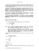
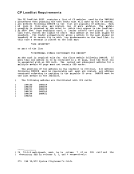
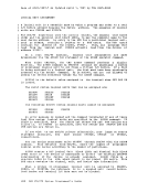
Assembler Virtual Storage Requirements
Them1nlIDum 51ze virtual machine required by the assembler is bytes. However, better performance is generally achieved if
assembler is run in320K bytes of virtual storage. This size
recommended for medium and large assemblies.
256K
the
is
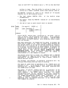
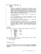
If more virtual storage is allocated to the assembler, the size of
buffers and work space can be increased.The amount of storage
allocated to buffers and work space determines assembler speed and
capacity. Generally, as more storage is allocated to work space, larger
and more complex macro definitions can be handled.You can control the buffer sizes for the assembler utility data sets (SYSUT1, SYSUT2, and SYSUT3), and the size of the work space used during
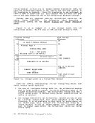
macro processing, by specifying theBUFSIZE assembler option. Of the
storage given, the assembler first allocates storage for theASSE8BLE and CMSLIB buffers according to the specifications in the DD statements
supplied by the FILEDEF for the data sets. It then allocates storage
for the modules of the assembler. The remainder of the virtual machine
is allocated to utility data set buffers and macro generation
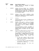
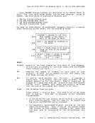
dictionaries according to theBUFSIZE option specified: BUFSIZE(STD): 37 percent is allocated to buffers, and 63
work space. This is the default if you do
anyBUFSIZE option.
percent to
not specifyBUFSIZE(MIN): Each utility data set is allocated a single 790-byte
buffer. The remaining storage is allocated to work
space. This allows relatively complex macro definitions
to be processed in a given virtual machine size, but the
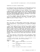
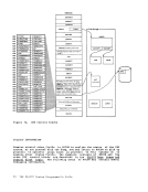
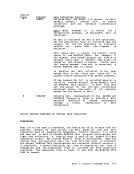
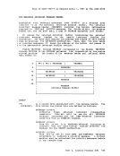
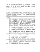
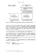
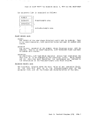
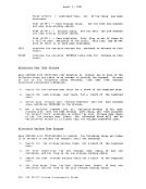
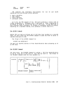
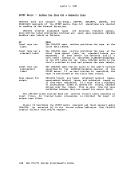
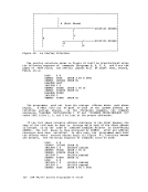
speed of the assembly is substantially reduced.Overlay Structures
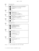
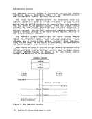
An overlay structure can be created inCMS in two different ways,
althoughCMS has no overlay supervision. For descriptions of all the CMS commands mentioned, see the PRESTRUCTURED OVERLAY A prestructured overlay program is created using the LOAD, INCLUDE, and GENMOD commands. Each overlay phase or segment is a nonrelocatable
core-image module created byGENMOD. The phases may be brought into
storagewith the LOADMOD command. Part 3. Conversational Monitor System (CMS) 323
The
assembler is run in
recommended for medium and large assemblies.
256K
the
is
If more virtual storage is allocated to the assembler, the size of
buffers and work space can be increased.
allocated to buffers and work space determines assembler speed and
capacity. Generally, as more storage is allocated to work space, larger
and more complex macro definitions can be handled.
macro processing, by specifying the
storage given, the assembler first allocates storage for the
supplied by the FILEDEF for the data sets. It then allocates storage
for the modules of the assembler. The remainder of the virtual machine
is allocated to utility data set buffers and macro generation
dictionaries according to the
work space. This is the default if you do
any
percent to
not specify
buffer. The remaining storage is allocated to work
space. This allows relatively complex macro definitions
to be processed in a given virtual machine size, but the
speed of the assembly is substantially reduced.
An overlay structure can be created in
although
core-image module created by
storage