Page of GC20-1807-7 As Updated April 1, 1981 by TNL GN25-0829
virtual machine traces external interrupts, the virtual interval timer
assist is automatically disabled. When external interrupt tracing is
completed, virtual interval timer assist is reenabled.
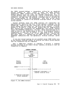
THEVIRTUAL BLOCK MULTIPLEXER CHANNEL OPTION virtual machine SIO operations are simulated by CP in three ways:
byte-multiplexer, selector, and block multiplexer channel mode.
virtual byte-multiplexer mode is reserved forI/O operations that
apply to devices allocated to channel zero.
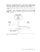
Selector channel mode (the default mode) is the mode of operation for
any channel that has an attached Channel-to-Channel Adapter(CTCA), regardless of the selected channel mode setting (the CTCA is treated as
a shared control unit and, therefore, it must be connected to a selector
channel). The user need not concern himself as to the location of theCTCA since CP interrogates the related channel linkage and marks the
channel as being in selector mode. As in real selector channel
operations,CP reflects a busy condition (condition code 2) to the
virtual machine's operating system if the system attempts a secondSIO to the same device, or another device on the same channel, before the
firstSIO is completed.
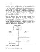
Block multiplexer channel mode is aCP simulation of real block
multiplexer operation; it allows the virtual machine's operating system
to overlapSIO requests to multiple devices connected to the same
channel. The selection of block multiplexer mode of operation may
increase the virtual machine's throughput, particularly for those
systems or programs that are designed to use the block multiplexer
channels.
Note:CP simulation of tlock multiplexer processing does not reflect
channel available interruptions(CAls) to the user's virtual machine.
Selecting the channel mode of operation for the virtual machine can
be accomplishedby either a system generation DIRECTORY OPTION operand
or by use of theCP DEFINE command.
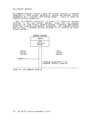
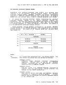
ALTERNATE PATHSUPPORT Through the use of the Two-Channel Switch and Two-Channel Switch
Additional Features, alternate path support for DASD or tape provides
for up to four channels on one control unit to be attached toVM/370. In addition, one device may te attached to two logical control units,
providing support for the String Switch feature. This allows the
control program up to eight paths to a given device when the maximum
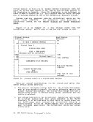
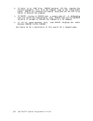
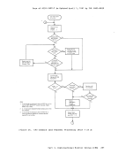
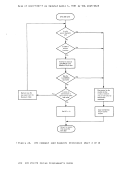
number of alternate channels and alternate control units are specified.When an I/O request is received for a device which has alternate
paths defined, theVM/370 lOS supervisor searches for an available path
beginning with the primary path to the device. If the primary path is
unavailable, the search continues with the first alternate path.
Successive alternate paths are examined if required until an available
path is found.102 TOM .J..J •. H . .l System programmer's Guide
virtual machine traces external interrupts, the virtual interval timer
assist is automatically disabled. When external interrupt tracing is
completed, virtual interval timer assist is reenabled.
THE
byte-multiplexer, selector, and block multiplexer channel mode.
virtual byte-multiplexer mode is reserved for
apply to devices allocated to channel zero.
Selector channel mode (the default mode) is the mode of operation for
any channel that has an attached Channel-to-Channel Adapter
a shared control unit and, therefore, it must be connected to a selector
channel). The user need not concern himself as to the location of the
channel as being in selector mode. As in real selector channel
operations,
virtual machine's operating system if the system attempts a second
first
Block multiplexer channel mode is a
multiplexer operation; it allows the virtual machine's operating system
to overlap
channel. The selection of block multiplexer mode of operation may
increase the virtual machine's throughput, particularly for those
systems or programs that are designed to use the block multiplexer
channels.
Note:
channel available interruptions
Selecting the channel mode of operation for the virtual machine can
be accomplished
or by use of the
ALTERNATE PATH
Additional Features, alternate path support for DASD or tape provides
for up to four channels on one control unit to be attached to
providing support for the String Switch feature. This allows the
control program up to eight paths to a given device when the maximum
number of alternate channels and alternate control units are specified.
paths defined, the
beginning with the primary path to the device. If the primary path is
unavailable, the search continues with the first alternate path.
Successive alternate paths are examined if required until an available
path is found.