April 1, 1981
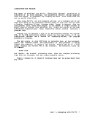
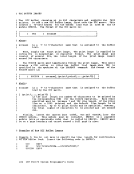
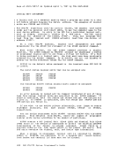
In the payroll control module(PAYROLL), the subroutine DMSLADAD must
be called to establish the linkage to
call must be executed before any call is made to a payroll module that
is in thePAYDIRT auxiliary directory.
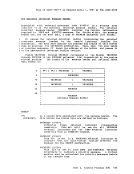
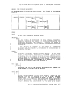
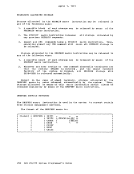
LA R1,PLIST SVC 202 DC AL4 (ERRTN) PLIST DS OF DC CL8' DMSLADAD' DC V(PAYDIRT) DC F'O' Next, all payroll modules must have their absolute core-image files
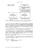
generated and the payroll auxiliary directory must be initialized. In
the example, the payroll control module(PAYROLL) is given a mode number
of 2 while the other payroll modules are given a mode number of 1.When the PAYROLL program is finally executed, only the files on the 194 disk
with a mode number of 2 will be accessed. This means only thePAYROLL control program (which includes the payroll auxiliary directory) will be
referenced from the resident directory. All the other payroll modules,
because they have mode numbers of 1, will be referenced via the payroll
auxiliary directory.
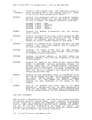
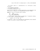
The following sequence of commands will
core-image files for the payroll modules and
auxiliary directory.ACCESS 194 A
create the absolute
initialize the payrollLOAD PAYROLL PAYDIRT GENKOD PAYROLL (now the auxiliary directory is included in the
payroll control module, but it is not yet
ini tialized. )LOADMOD PAYROLL INCLUDE PAYROLL1 GEN MOD PA YROLL 1 (this sequence of three commands is repeated fo
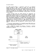
eacb payroll module called byPAYROLL.) LOADMOD PAYROLL INCLUDE PAYSHIFT GENMOD PAYSHIFT LOADMOD PAYROLL GENDIRT PAYDIRT Y GENMOD PAYROLL MODULE A2 When it is time to execute the PAYROLL program, the 194 disk must be
accessed as theY disk (the same mode letter as specified on the GENDIRT
command). Also, the 194 disk is accessed in a way that includes thePAYROLL control program in the resident directory but not the other
payroll modules. This is done by specifying a mode number of 2 on theACCESS command. ACCESS 194 Y/S * * Y2 NOW, a request for a payroll module, such
successfully fulfilled. The auxiliary directoryPAYOVERT will be found on the Y disk.
asPAYOVERT, can be
will be searched andNgte: A disk referred to by an auxiliary directory must be accessed as a
read-only disk.
322IBM VM/370 System Programmer's Guide
In the payroll control module
be called to establish the linkage to
call must be executed before any call is made to a payroll module that
is in the
LA R1,
generated and the payroll auxiliary directory must be initialized. In
the example, the payroll control module
of 2 while the other payroll modules are given a mode number of 1.
with a mode number of 2 will be accessed. This means only the
referenced from the resident directory. All the other payroll modules,
because they have mode numbers of 1, will be referenced via the payroll
auxiliary directory.
The following sequence of commands will
core-image files for the payroll modules and
auxiliary directory.
create the absolute
initialize the payroll
payroll control module, but it is not yet
ini tialized. )
eacb payroll module called by
accessed as the
command). Also, the 194 disk is accessed in a way that includes the
payroll modules. This is done by specifying a mode number of 2 on the
successfully fulfilled. The auxiliary directory
as
will be searched and
read-only disk.
322