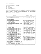
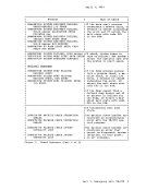
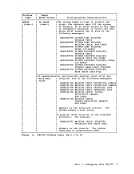
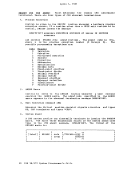
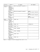
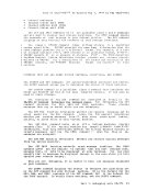
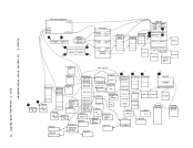
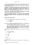
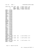
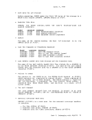
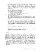
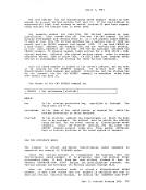
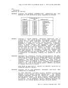
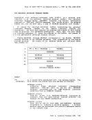
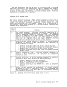
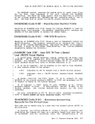
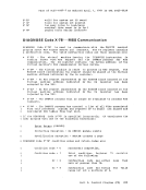
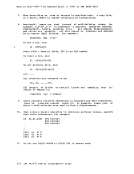
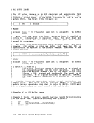
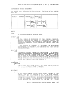
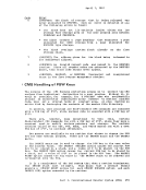
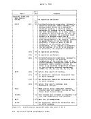
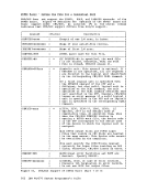
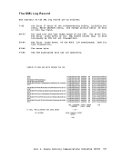
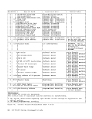
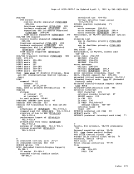
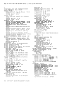
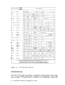
characters. A data record to be transmitted is segmented into the
optimum number of character strings (to take full advantage of the
identical character compression)by the transmitting program. A special
SCB is used to indicate the grouping of character strings that compose
the original physical record. The receiving program can then
reconstruct the original record for processing.
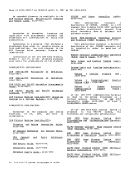
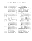
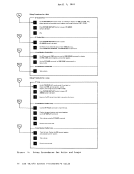
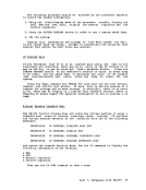
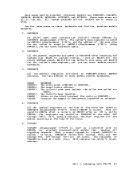
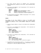
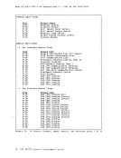
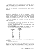
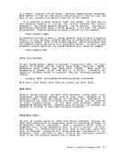
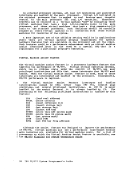
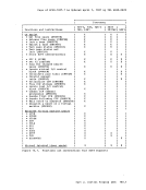
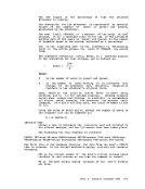
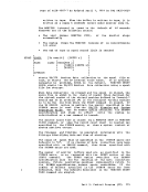
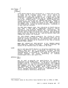
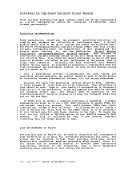
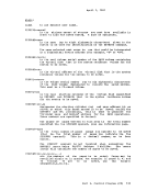
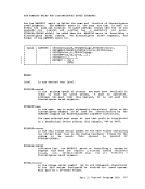
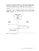
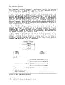
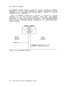
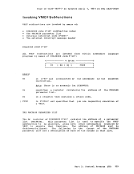
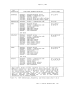
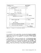
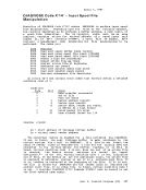
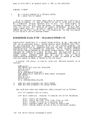
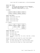
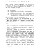
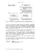
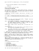
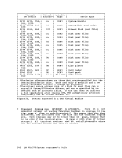
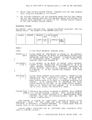
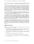
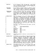
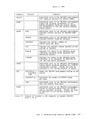
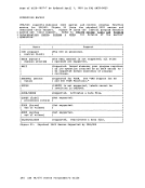
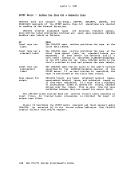
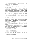
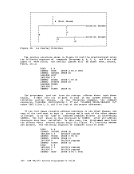
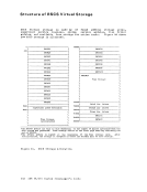
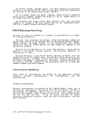
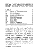
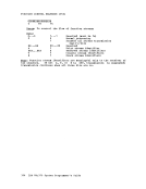
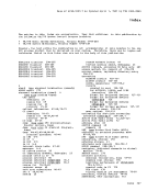
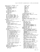
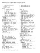
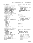
ControlI Characters I Usage I DLE STX BCB FCS FCS
RCB
SRCB
SCB
DATA
SCB
DATA
SCB
RCB
SRCB
SCB
DATASCB RCB
DLE
ETB
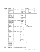
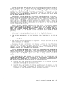
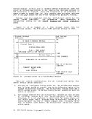
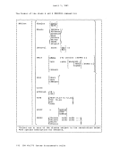
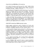
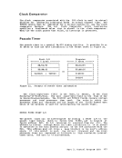
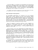
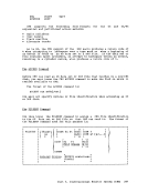
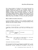
Figure 48.• BSC Leader (SOH if no transparency feature)
BSC Start-of-Text
Block Control Byte
Function Control Sequence
Function Control Sequence
Record Control Byte for record 1
Sub-Record Control Byte for record 1
String Control Byte for record 1
Character String
String Control Byte for record 1
Character String
Terminating SCB for record 1
RCB for record 2
SRCB for record 2
SCB for record 2
Character String
Terminating SCB for record 2
Transmission Block terminatorBSC Leader (SIN if no transparency feature)
BSC Ending Sequence
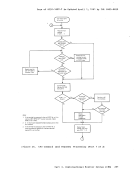
A TypicalMULTI-LEAVING Transmission Block
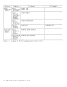
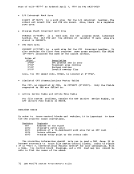
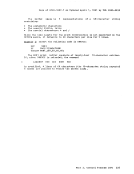
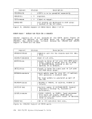
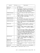
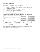
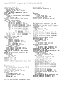
In order toallow multiple physical records of various types to be
grouped together in a single transmission block (see Figure 48), an
additional eight-bit control field precedes the group of character
strings representing the original physical record. This
Record Control Byteof the physical record (input stream, print stream, data set, etc.). A
particular RCB type has been designated to allow the passage of control
information betwe.en the various systems. Also, to provide for
simultaneous transmission of similar functions (that is, multiple input
streams, etc.), a stream identification code is included in the RCB. A
second eight-bit control field, the Sub-Record Control Byte (SRCB), is
also included immediately following the RCB. This field is used to
supply additional information concerning the record to the
SRCB can be used for carriage control information.
For actualMULTI-LEAVING transmission, a variable number of records
may be combined into a variable block size, as indicated previously
(that is, RCB,SRCB,SCB1,SCB2,••• ,SCBn, RCB,SRCB,SCB1, ••• MULTI-LEAVING design provides for two (or more) computers to exchange
transmission blocks, containing multiple data streams as described
above, in an interleaved fashion. To allowoptimum use of this
capability, however, a system must have the capability to control the
flow of a particular data stream while continuingnormal transmission cf
all others. This requirement becomes obvious if one considers the case
of the simultaneous transmission of two data streams to a system for
immediate transcription to physicalI/O devices of different speeds
(such as two print streams).350 IBM'VM/370 System Programmer's Guide
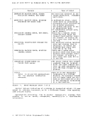
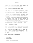
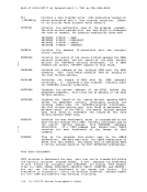
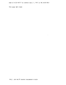
optimum number of character strings (to take full advantage of the
identical character compression)
SCB is used to indicate the grouping of character strings that compose
the original physical record. The receiving program can then
reconstruct the original record for processing.
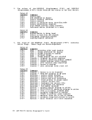
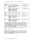
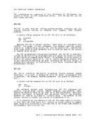
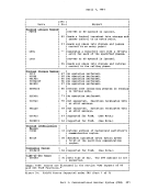
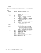
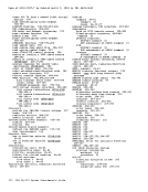
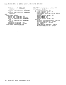
Control
RCB
SRCB
SCB
DATA
SCB
DATA
SCB
RCB
SRCB
SCB
DATA
DLE
ETB
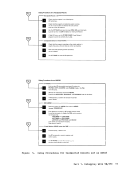
Figure 48
BSC Start-of-Text
Block Control Byte
Function Control Sequence
Function Control Sequence
Record Control Byte for record 1
Sub-Record Control Byte for record 1
String Control Byte for record 1
Character String
String Control Byte for record 1
Character String
Terminating SCB for record 1
RCB for record 2
SRCB for record 2
SCB for record 2
Character String
Terminating SCB for record 2
Transmission Block terminator
BSC Ending Sequence
A Typical
In order to
grouped together in a single transmission block (see Figure 48), an
additional eight-bit control field precedes the group of character
strings representing the original physical record. This
Record Control Byte
particular RCB type has been designated to allow the passage of control
information betwe.en the various systems. Also, to provide for
simultaneous transmission of similar functions (that is, multiple input
streams, etc.), a stream identification code is included in the RCB. A
second eight-bit control field, the Sub-Record Control Byte (SRCB), is
also included immediately following the RCB. This field is used to
supply additional information concerning the record to the
SRCB can be used for carriage control information.
For actual
may be combined into a variable block size, as indicated previously
(that is, RCB,SRCB,SCB1,SCB2,
transmission blocks, containing multiple data streams as described
above, in an interleaved fashion. To allow
capability, however, a system must have the capability to control the
flow of a particular data stream while continuing
all others. This requirement becomes obvious if one considers the case
of the simultaneous transmission of two data streams to a system for
immediate transcription to physical
(such as two print streams).