VM370 System Programmers Guide (Rel6)
Page60(83 of 430)
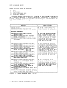
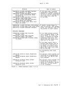
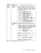
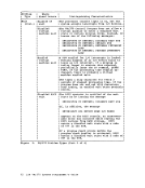
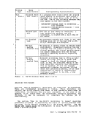
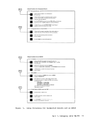
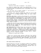
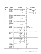
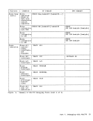
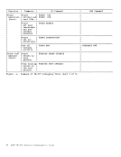
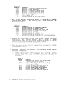
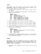
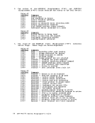
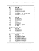
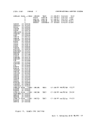
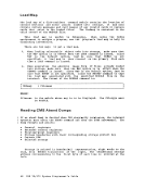
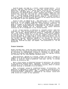
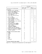
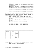
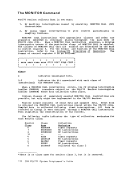
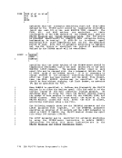
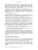
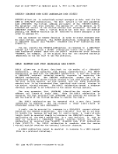
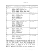
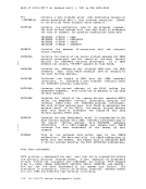
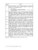
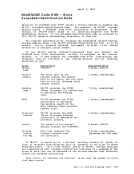
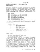
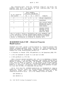
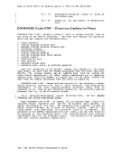
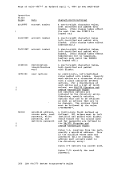
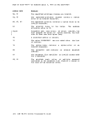
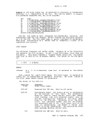
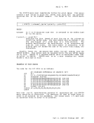
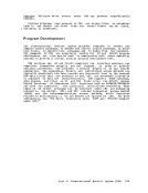
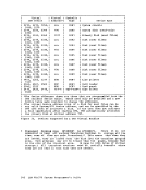
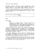
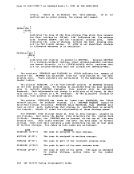
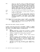
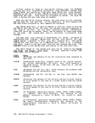
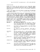
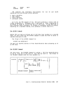
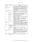
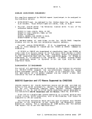
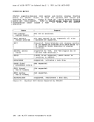
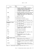
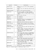
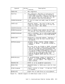
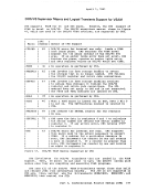
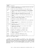
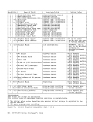
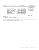
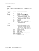
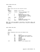
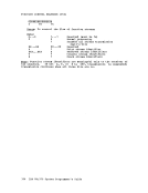
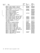
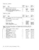
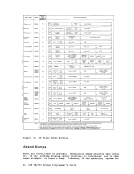
r April 1, 1981 • For Special Device Class Code i'eo' X' 40' X' 20' X' ou· X' 01' Channel-to-Channel Adapter (CTCA) 370x Programmable Communications Controller 3851 Mass storage Controller S RF (7443) device Device unsupported by VM/370 MODEL CODES (Column 35 in Accounting Card) As specified in the RDEVICE macro at system generation. FEATURE CODES (Column 36 in Accounting Card) • For Printer Devices X'01' • For Magnetic Tape Devices X· 80' X'UO' X' 20' X' 10' Igat.!IT.§ 7-Track Dual Density Translate Data Conversion • For Direct Access storage Devices X' 80' X' 40' X' 20' X, 10' X'08' X' 04' X' 02' X' 01' Feature RotatIonal posit.ion Sensing (RPS) Extended Sense Bytes (24 bytes) Top Half of 2314 Used as 2311 Bottom Half of 2314 Used as 2311 35MB Data Module (mounted) 70MB Dat a Module (mounted) Reserve/Felease are valid CCW operation codes 3330V virtual MSS volume • For special devices X' 10' X'20' Feature Type-r-channel adapter for 370X Type II channel adapter for 370X L Figure 10. CP Device Classes, Types, Models, and Features (Part 3 of 3) n2 IBM Gui1e
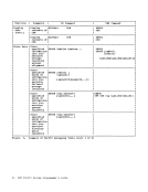
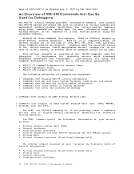
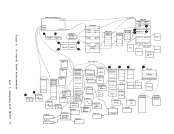
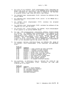
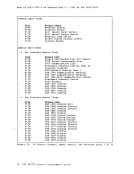
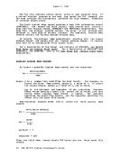
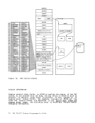
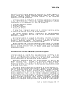
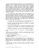
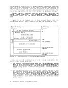
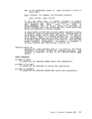
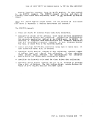
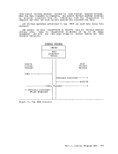
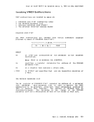
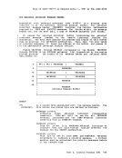
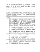
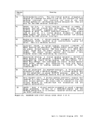
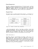
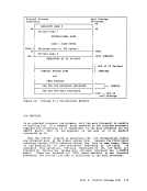
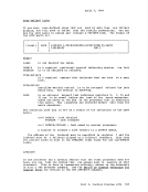
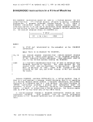
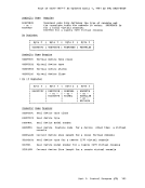
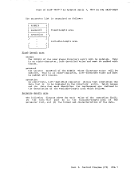
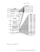
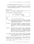
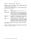
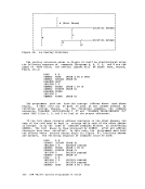
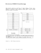
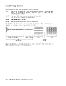
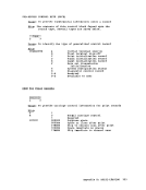
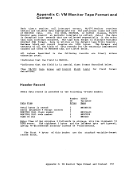
page of GC20-t801-7 As Updated April 1, 1981 by TNL GN25-0829 IDENTIFYING AND LOCATING A PAGEABLE MODULE If a proqram check PSW or SVC PSi points to an address beyond the end of the CP resident nucleus, the failing module is a pageable module. The CP system load map identifies the end of the resident nucleus. Go to the address indicated in the PSW. Backtrack to the beginning of tggi paqe frame. The first eight bytes of that page frame (the page frame containinq the address pointed to by the PSW) contains the name of the first pageable module loaded into the page. If multiple modules exist within the same page frame, identify the module using the load map and failing address displacement within the page frame. In most cases, register 12 will point directly to the name. To locate a pageable module whose address 1S shown in the load map; use the system VMBLOK segment and page tables. For example, if the address in the load map is 55000, use the segment and page tables to locate the module at segment 5, page 5. VMDUMP RECORDS: FORMAT AND CONTENT When a user issues the VMDUMP command, CP dumps virtual storage of the user's virtual machine. CP stores this dump on the reader spool file of a virtual machine that the user specified as an operand on the VMDUMP command. CP writes the storage dump to the spool file as a series of logical records. Each spool file record and each logical dump record is 4096-bytes long. However, because each spool file record contains a header, one logical dump record does not fit into one spool file record. For this reason, CP splits a logical dump record into two parts. CP writes one part to one spool file record and the other part to an adjacent spool file record. The size of each part varies depending upon the of space remaining in the spool file record that CP is currently usinq. Thus, each logical dump record spans two spool file records. Fiqure 10.1 shows the format of spool file records, the format of loqical dump records, and how loqical dump records span spool file records. The first spool file record contains a spool page buffer linkage block (SPLINK) followed by a TAG area followed by dump information. All other spool file records contain only a SPLINK followed by dump information. A SPLINK, which contains data needed to locate information in the associated spool file record, has the following format: hexadecimal Q!l§gi o 4 8 C lengih 4 bytes 4 bytes 4 bytes 4 bytes content the DASD location-(DCHR) of the next page buffer the DASD location (DCHR) of the previous page buffer binary zeros the number of data records in the buffer Part 1. Debugging with VM/310 63