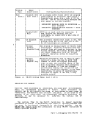
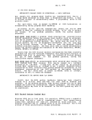
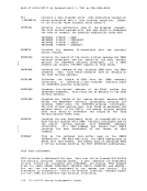
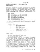
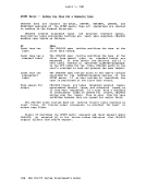
The MONITOR Command VM/370 Monitor collects data in two ways:
1. By handling interruptions caused by executinqMONITOR CALL (MC) instructions.
2. By usinq timer interruptions to
sampling-routines.rriuo :;,--- periodically to MONITOR CALL instructions with appropriate classes and codes are
presently embedded in strategic places throughout the main body ofVM/370 code (CP). When a MONITOR CALL instruction executes, a program interruption occurs if the particular class of ftONITOR CALL is enabled.
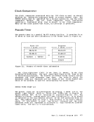
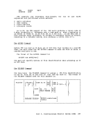
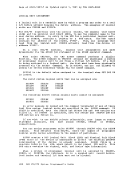
The classes ofMONITOR CALL that are enabled are determined by the mask
in control register 8. For the format and function of theMONITOR CALL
instruction, refer to the
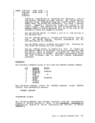
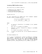
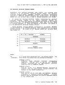
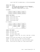
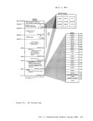
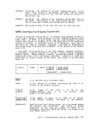
format of control register 8 is as follows:
1I I I I I I I I xxxx xxxx xxxx xxxx 0123 4567 89AB CDEF I I I I I I I I I x indicates unassigned bits. O-F (hexadecimal)
indicates the bit associated with each class of
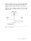
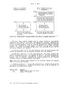
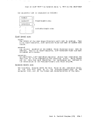
theMONITOR CALL. When a MONITOR CALL interruption occurs, the CP proqram interruption
handler(DMKPRG) transfers control to the VM/370 Monitor interruption
handler(DMKMON) where data collection takes place.
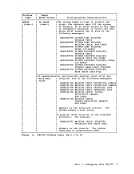
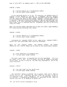
Sixteen classes of separately enabledMONITOR CALL instructions are
possible, but only eight are implemented in theVM/370 Monitor. Monitor output consists of event data and sampled data. Event data
is obtained viaMONITOR CALL instructions placed within the VM/370 code.
Sampled data is collected following timer interruptions. All data is
recorded as though it were obtained through aMONITOR CALL instruction.
This simplifies the identification of the records.
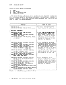
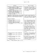
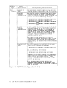
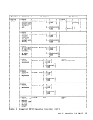
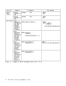
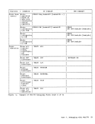
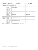
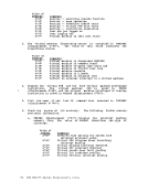
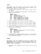
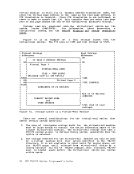
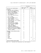
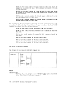
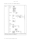
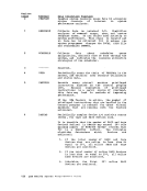
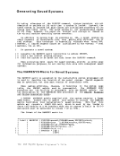
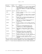
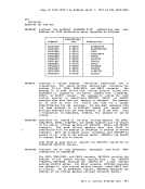
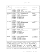
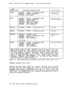
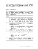
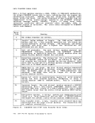
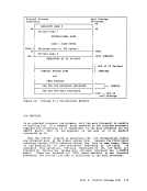
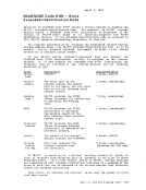
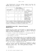
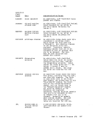
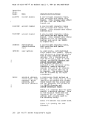
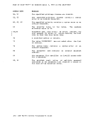
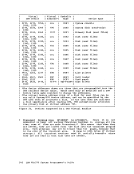
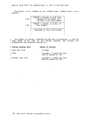
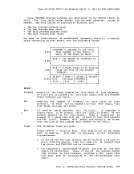
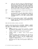
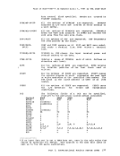
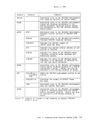
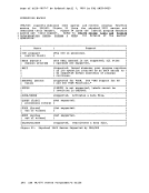
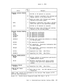
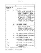
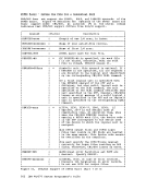
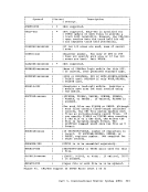
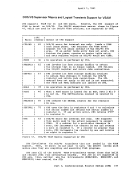
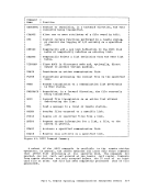
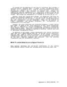
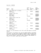
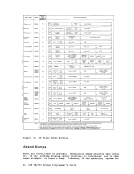
The following table indicates the type of collection mechanism for
each Monitor class:
Monitor Class Collection0 PERFORM rIier-requests 1 RESPONSE MC instructions
2SCHEDULE MC instructions
3
1
4USER Timer requests
5INSTSIM MC instructions
6DASTAP Timer requests
7SEEKS MC instructions
8SYSPROF Collected via class 2 IThere is no class name for monitor class 3, but it is reserved. 110 V!/370 System
1. By handling interruptions caused by executinq
2. By usinq timer interruptions to
sampling-routines.
presently embedded in strategic places throughout the main body of
The classes of
in control register 8. For the format and function of the
instruction, refer to the
format of control register 8 is as follows:
1
indicates the bit associated with each class of
the
handler
handler
Sixteen classes of separately enabled
possible, but only eight are implemented in the
is obtained via
Sampled data is collected following timer interruptions. All data is
recorded as though it were obtained through a
This simplifies the identification of the records.
The following table indicates the type of collection mechanism for
each Monitor class:
Monitor Class Collection
2
3
1
4
5
6
7
8