Clock Comparator
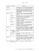
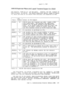
The clock comparator associated with the TOD clock is used in virtual
machines for generating interrupts based on actual elapsed time. The ECMODE option must be specified for a virtual machine to use the clock
comparator feature. The Set Clock Comparator (SCKC) instruction
specifies a doubleword value that is placed in the clock comparator.
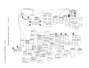
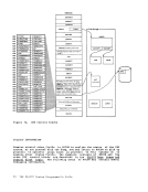
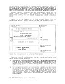
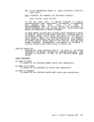
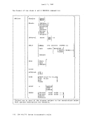
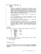
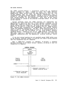
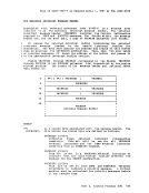
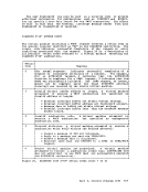
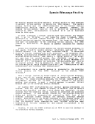
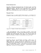
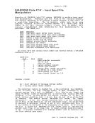
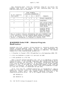
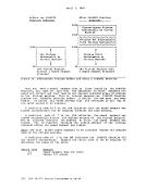
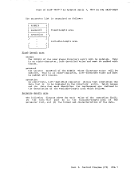
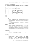
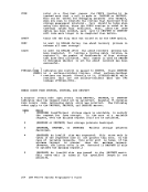
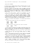
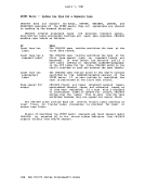
 When the TOD clock passes that value, an interrupt is generated.
Pseudo Timer
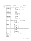
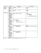
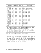
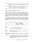
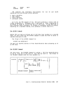
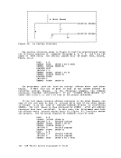
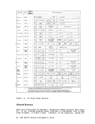
The pseudo timer is a special VM/370 timing facility. It provides 24 or
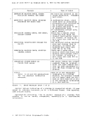
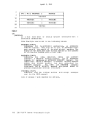
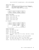
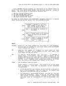
32 bytes of time and date information in the format shown in Figure 22.
Figure 22. Formats of Pseudo Timer Information
The first eight-byte field is the date, in EBCDIC, in the form Month/Day-of-Month/Year. The next eight-byte field is the Time of Day
in Hours:Minutes:Seconds. The VIRTCPU and TOTCPU fields contain virtual
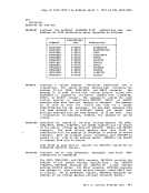
processor and total processor time used. The units in which the
processor times are expressed and the length of the fields depend upon
which of two methods is used for interrogating the pseudo timer. PSEUDO TIMER START I/O The pseudo timer can be interrogated by issuing a START I/O to the
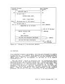
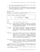
pseudo timer device, which is device type TIMER, and is usually at
device address OFF. No I/O interrupt is returned from the SIO. The
address in virtual storage where the timer information is to be placed
is specified in the data address portion of the CCi associated with the SID. This address must not cross a page boundary in the user's address space. If this method is used
6
the virtual Frocessor and the total
processor times are expressed as fullwords in high resolution interval
timer units. One unit is 13 microseconds. Part 2. Control program (CP) 177
PSEUDO TIMER DIAGNOSE
The pseudo timer can also be interrogated by issuing DIAGNOSE with an
operation code of C, as described under "DIAGNOSE Instruction in a Virtual Machine." If this method is used, the virtual and total
processor times are expressed as double words in microseconds.
CP In Attached Processor Mode
In an attached processor environment, two processors share main storage.
There is special code in CP to ensure that the two processors do not
interfere in each other's operation. Most of this special code is
executed only in an attached processor environment. For information about system generation of the special code, see the glanning PSA Each processor needs its own area for processor-related information.
During CP initialization, CP obtains an area from the high-end of real
storage for prefix storage areas (PSA) for each processor. Each
processor accesses its own PSA by a process called prefixing. Prefixing is described in detail in the B! (GA22-7000) • When code executing on either processor references an address from 0 to 4096, the referenced address is added to the contents of the prefix
register for that processor to produce the "absolute" address that will
be accessed. A reference to the first 4K of storage, therefore, results
in the PSA residing in high core being accessed. In this way, each
processor is given its own work area and save areas. Figure 23, a
storage map of the V=R machine, shows where PSAs are located in real
storage after CP initialization completes. However, if a processor is
varied offline and then online after CP initialization completes, the
processor's PSA may be located in any contigeous 4K byte area of free
storage. IBM VM/370 System Programmer's Guide
Previous Page Next Page