The following procedure should be followed by the processor operator
to record the needed information.
1.Using the alter/display mode of the processcr console, display the
realPSW and CSW. Also, display the general registers and the
control registers.
2. Press theSYSTEM RESTART button in order to get a system abend dump.
3.IPL the system.
Examine this information and attempt to find what caused thewait. If you cannot find the cause, attempt to reconstruct the situation that
existed just before the wait state was entered.
If you determine thatCP is in an enabled wait state, but that no IIO interrupts are occurring, there may be an error in the CP routine or CP aay be failing to get an interrupt from a hardware device. Press the SYSTEM RESTART button on the operator's console to cause an abend dump
to hetaken. Use the ahend dump to determine the cause of the enabled
(and noninterrupted) wait state. After the dump is taken,IPL the
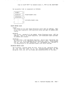
system.Using the dump, examine the VMBLOK for each user and the real device,
channel, and control unit blocks.. If each user is waiting because of a
request for storage and no more storage is available, there is an error
inCP. There may be looping in a routine that requests storage. Refer to
-ReadingCP Abend Dumps" for specific information on how to analyze a CP du.p.
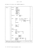
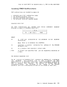
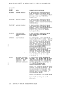
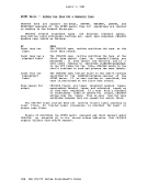
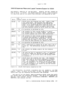
TheVM/370 Control Program does not allow the virtual machine to enter a
disabledwait state or certain interrupt loops& Instead, CP notifies
the virtual machine operator of the condition with one of the following
aessages:DMKDSP450W CP ENTERED; DISABLED WAIT PSW DMKDSP451W CP ENTERED; INVALID PSi DMKDSP452W CP ENTERED; EXTERNAL INTERRUPT LOOP DMKPRG453W CP ENTERED; PROGRAM INTERRUPT LOOP and enters the console function .ode. Use the CP commands to display the
following information on the terminal.• PSW • CSW • General registers • Control registers
Then use theCP DUMP command to take a dump. Part 1. Debugging with V8/370 29
to record the needed information.
1.
real
control registers.
2. Press the
3.
Examine this information and attempt to find what caused the
existed just before the wait state was entered.
If you determine that
to he
(and noninterrupted) wait state. After the dump is taken,
system.
channel, and control unit blocks.. If each user is waiting because of a
request for storage and no more storage is available, there is an error
in
-Reading
The
disabled
the virtual machine operator of the condition with one of the following
aessages:
following information on the terminal.
Then use the