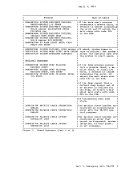
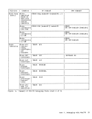
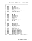
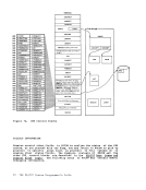
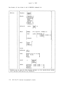
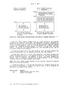
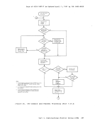
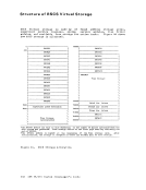
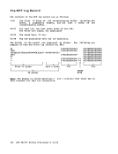
page of GC20-1807-7 As Updated April 1, 1981 by TNL GN25-0829 your viLtual machine cannot continue, it terminates and, in some cases,
attempts to issue a dump. In theVM/370 environment, the problem proq-r-am-dum-palwa-ys- goes - t-othe- v-irtllal- _printer. De-ItendiJ)_q
dumpmay also go to the virtual printer. A CLOSE must be issued to the
virtual printer to have either dump print on the real printer.
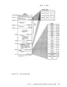
The third type of dump occurs when theCP system cannot continue.
TheCP abnormal termination dumps can be directed to a printer or tape
or be dynamically allocated toDASD. If the dump is directed to a tape,
the dumped data must fit on one reel of tape. Multiple tape volumes are
not supported byVM/370. The historical data on the tape is in print
line format and can be processed by user-created programs or viaCMS commands. specify the output device for CP abend dumps with the CP SET command. When the CP abend dump is sent to a disk, use the CMS VMFDUMP command
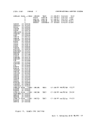
to print the dump on the real printer.Use the VMFDUMP command to format and print a current or previous VM/370 system abend dump. Specify VMFDUMP to obtain a complete formatted, hexadecimal printout. When the dump has been printed, one of two messages will be printed. DUMP FILE - DUMP xx - PRINTED AND KEPT
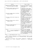
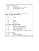
-- or --DUMP FILE - DUMP xx -PRINTED AND ERASED. HOW TO PRINT A CP ABEND DUMP FROM TAPE When the CP abend dump is sent to a tape, the records are 131 characters
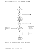
long, unblocked, and contain carriage control characters.
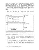
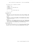
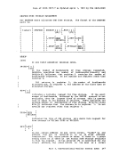
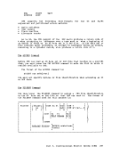
TopLint the tape, first make sure the tape drive is attached to your
system. Next, define the printer and tape file.
FILEDEF ddname1 PRINTER (RECFM FM LRECL 131)
FILEDEF ddname2 {TAP2} (DEN1600 RECFM U LRECL 132) TAP1 Then use the MOVEFILE command to print the tape: MOVEFILE ddname2 ddname1
An extended form of theVMFDUMP command may be used via the facilit.les cit IPCS (In-teracti-v-e-- Problem Cont.rolSystem)- by- Field
EnqineeLing ProgramSystems Representatives, and by installation system
programmers. For information onIPCS, refer to the publication !K/31g (lgcS) Part 1. Debugging with VM/370 45
attempts to issue a dump. In the
dump
virtual printer to have either dump print on the real printer.
The third type of dump occurs when the
The
or be dynamically allocated to
the dumped data must fit on one reel of tape. Multiple tape volumes are
not supported by
line format and can be processed by user-created programs or via
to print the dump on the real printer.
-- or --
long, unblocked, and contain carriage control characters.
To
system. Next, define the printer and tape file.
FILEDEF ddname1 PRINTER (RECFM FM LRECL 131)
FILEDEF ddname2 {TAP2} (DEN
An extended form of the
EnqineeLing Program
programmers. For information on