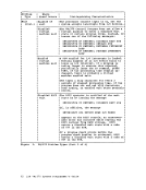
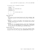
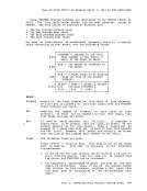
2. Examine the SVC old PSi, the SVC interrupt code, and the abend code
to find whether or not aCP routine issued an SVC O. The SVC old PSi {SVCOPSW} is located at 1'20', the SVC interrupt code (INTSVC) is at X'8A', and the abend code (CPABEND) is at X'314'. The abend code (CPABEND) is a fullword. The first three bytes
identify the module that issued theSVC 0 and the fourth bite is a
binary field whose value indicates the reascn for issuing anSVC O. Use the CP system load map to identify the module issuing the SVC O. If you cannot find the module using the CP system load map. refer to "Identifying a Pageable Module". Figure 41 in Appendix A
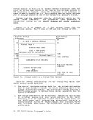
describes the format of an Extended ControlPSi. 3. Examine the old PSi at X
1
08'. If an abnormal termination occurs
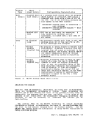
because the operator pressed the system restart button, the oldPSi at location X'08' points to the instruction that was executing when CP recognized the abnormal termination. Figure 41 in Appendix A describes the format of an Extended Control PSi. 4. For a machine check, examine the machine check old PSi and the
logout area. The machine check oldPSi (8COPSi) is found at X'30' and the fixed logout area is at X
1
100'. Also examine the machine
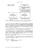
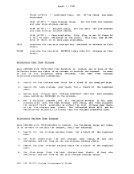
check interrupt code(INTMC) at X'E8'. COLLECT INFORMATION Examine several other fields in the PSA to analyze the status of the
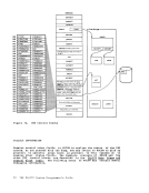
system. As you progress in reading the dump, you may return to thePSA to pick up pointers to specific areas (such as pointers to the real
control blocks) or to examine other status fields.
The following areas of the
information.PSA may contain useful debugging
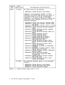
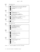
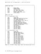
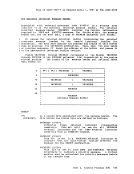
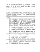
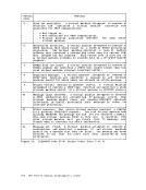
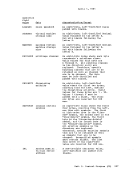
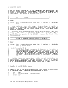
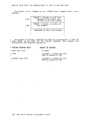
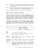
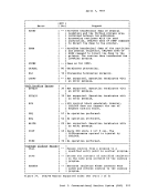
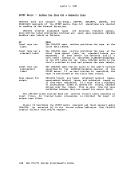
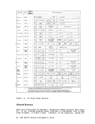
1.CP Running Status Field
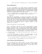
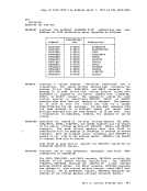
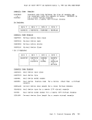
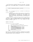
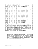
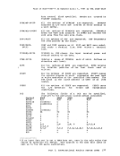
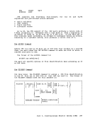
TheCP running status is stored in CPSTAT at location X'348'. The
value of this field indicates the running status ofCP since the
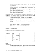
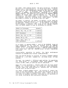
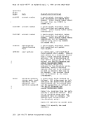
last entry to the dispatcher.Value of X'80' X'40' X'20' X'08' 2. Current User Comments cp-Is-In wait state CP is running the user in RONUSER CP is executing a stacked request CP is running in supervisor state
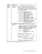
ThePSi that was most recently loaded by the dispatcher is saved in RUNPSW at location X'330', and the address of the dispatched RUNUSER at location X'338'. Also, examine the contents
of control registers0 and 1 as they were when the last PSi was
dispatched.See RUNCRO (X'340') and RONCR1 (X'344') for the
control registers.Part 1. Debugging with V8/310 41
to find whether or not a
identify the module that issued the
binary field whose value indicates the reascn for issuing an
describes the format of an Extended Control
1
08'.
because the operator pressed the system restart button, the old
logout area. The machine check old
1
100'.
check interrupt code
system. As you progress in reading the dump, you may return to the
control blocks) or to examine other status fields.
The following areas of the
information.
1.
The
value of this field indicates the running status of
last entry to the dispatcher.
The
of control registers
dispatched.
control registers.