October 1, 1979 FORMATTING ALTER CODES
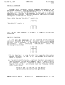
GRID
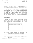
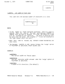
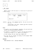
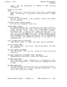
STEP-BY-STEP EXAMPLE ____________________
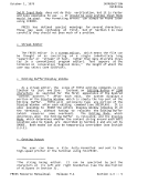
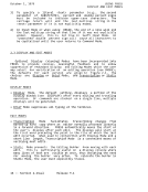
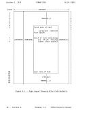
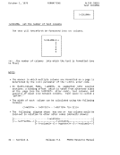
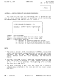
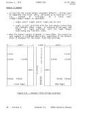
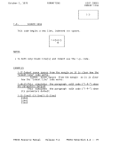
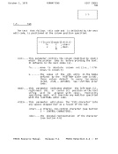
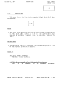
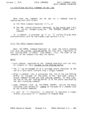
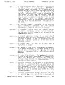
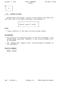
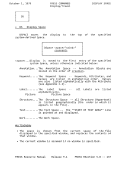
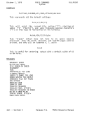
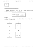
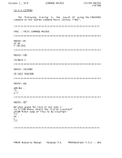
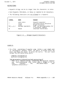
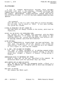
The following is a step-by-step example of how the square grid
used in Figure 4-3 was produced. In each step, additions to the
GRID code are underlined.
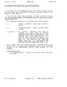
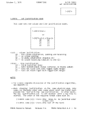
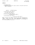
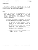
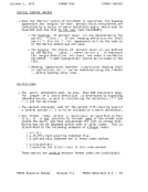
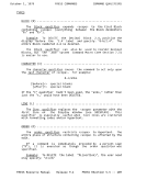
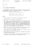
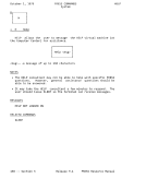
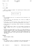
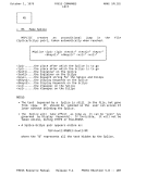
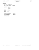
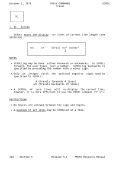
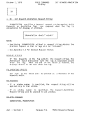
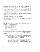
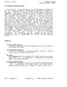
1. The grid was to start in column 24, after skipping two blank
lines on the page. Text within the grid was to start in
column 26. (discussion is limited to the grid on the right in
Figure 4-3.) To position the grid correctly, the following
edit and alter codes were used:
!+settab1=24;3=30;4=34+
!-s2;t1-!+grid...
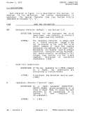
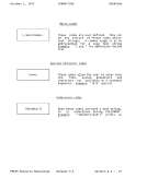
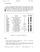
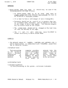
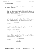
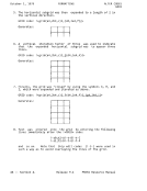
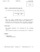
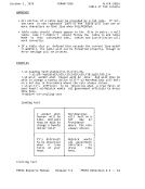
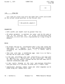
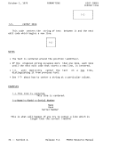
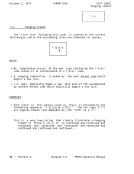
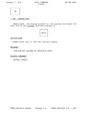
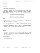
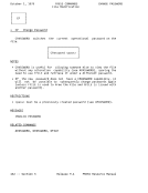
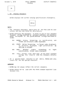
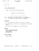
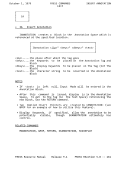
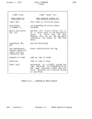
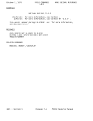
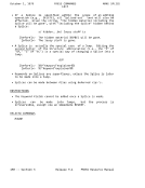
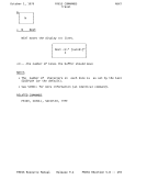
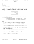
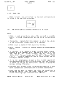
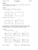
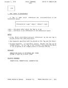
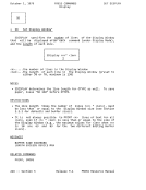
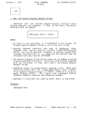
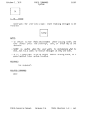
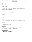
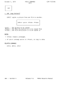
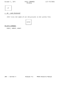
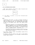
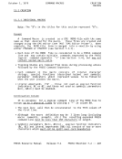
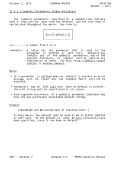
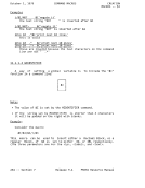
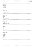
2. To "draw" the top line, the grid symbols A, B, and C were
needed. A and B were expanded to a length of 4 characters in
the horizontal direction, and the pattern generated by the
string B4 was needed twice (an iteration factor of two).
(a4,2b4,c) GRID code: !+grid__________+
Generates:
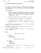
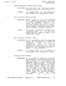
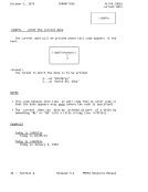
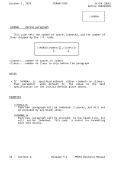
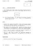
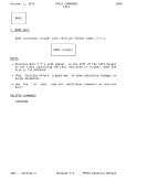
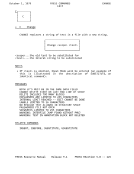
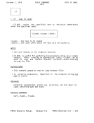
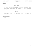
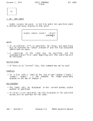
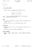
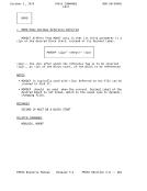
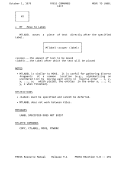
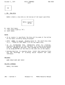
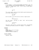
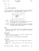
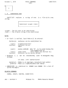
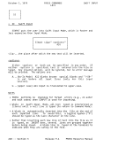
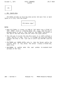
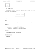
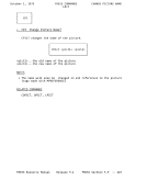
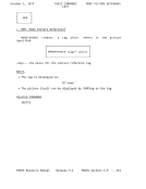
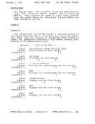
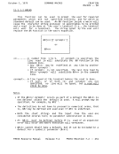
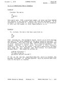
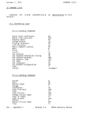
3. The top line of the grid had to be expanded to a length of
two in the vertical direction; this was done by placing the
vertical expansion number "2" after the row.
2 GRID code: !+grid(a4,2b4,c)_+
Generates:
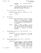
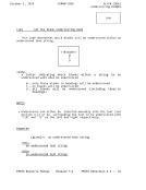
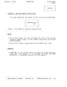
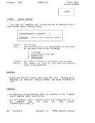
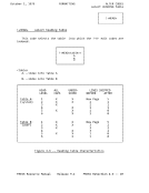
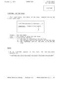
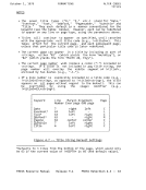
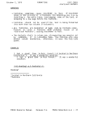
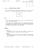
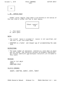
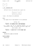
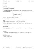
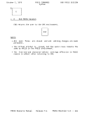
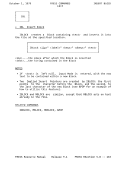
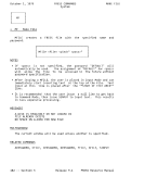
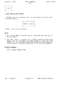
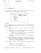
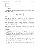
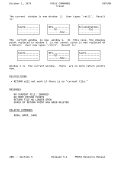
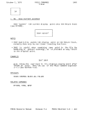
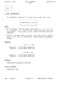
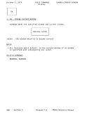
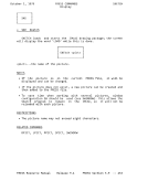
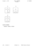
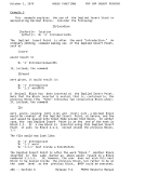
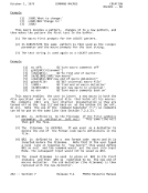
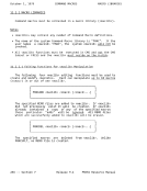
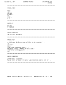
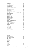
4. Using the grid symbols D, E, and F, a horizontal subgrid was
added to the grid. As in step 1, symbols D and E were
expanded and an iteration number was used to generate the
pattern represented by "E4" twice.
,(d4,2e4,f) GRID code: !+grid(a4,2b4,c)2___________+
Generates:
FRESS Resource Manual Release 9.1 FRESS ReSection 4.3 -- 45
GRID
STEP-BY-STEP EXAMPLE ____________________
The following is a step-by-step example of how the square grid
used in Figure 4-3 was produced. In each step, additions to the
GRID code are underlined.
1. The grid was to start in column 24, after skipping two blank
lines on the page. Text within the grid was to start in
column 26. (discussion is limited to the grid on the right in
Figure 4-3.) To position the grid correctly, the following
edit and alter codes were used:
!+settab1=24;3=30;4=34+
!-s2;t1-!+grid...
2. To "draw" the top line, the grid symbols A, B, and C were
needed. A and B were expanded to a length of 4 characters in
the horizontal direction, and the pattern generated by the
string B4 was needed twice (an iteration factor of two).
(a4,2b4,c) GRID code: !+grid__________+
Generates:
3. The top line of the grid had to be expanded to a length of
two in the vertical direction; this was done by placing the
vertical expansion number "2" after the row.
2 GRID code: !+grid(a4,2b4,c)_+
Generates:
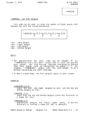
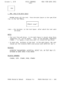
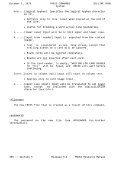
4. Using the grid symbols D, E, and F, a horizontal subgrid was
added to the grid. As in step 1, symbols D and E were
expanded and an iteration number was used to generate the
pattern represented by "E4" twice.
,(d4,2e4,f) GRID code: !+grid(a4,2b4,c)2___________+
Generates:
FRESS Resource Manual Release 9.1 FRESS ReSection 4.3 -- 45