load
Protection for
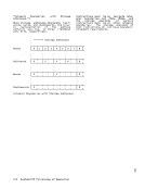
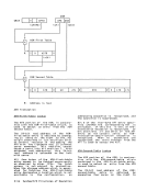
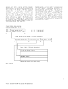
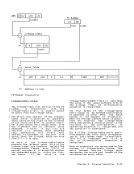
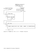
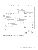
Trace-Table Designation
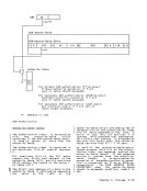
Trace-Table-Entry Header
Interlocks
Identification of
Instruction Fetching
General-Register Alteration
Read-Write-Direct Facility
Timing
Interval Timer
Initial Program Reset
Initial Program loading
store
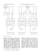
Multiprocessing
Conditions
Order