Programmjng Notes
1. Since no unit-status bits are set
to ones in theCSW associated with
the conclusion of an operation of a
selector channel by HALTI/O or
HALTDEVICE, unit-status bits and
thePCI bit set to ones are not
necessary for the operation to be
concluded. When status in a selec
tor channel includesPCI at the
time the operation is concluded by
HALTI/O or HALT DEVICE, the CSW associated with the concluded oper
ation is indistinguishable from theCSW provided by an interruption
during execution of the operation.
2. Program-controlled interruption
provides a means of alerting the
program to the progress of chaining
during anI/O operation. It
permits programmed dynamic storage
allocation.CHANNEL INDIRECT DATA ADDRESSING Channel indirect data addressing permits
a single channel-command word to control
the transmission of data that spans non
contiguous pages in absolute storage.Channel indirect data addressing is
specified by a flag bit in theCCW which, when one, indicates that the
data-address field is not used to
directly address data. The contents of
the data-address field specify the
location of an indirect-data-address
word (IDAW), which contains an absolute
address designatinga data area within
storage. An IDAW is used for the trans
fer of up to 2K bytes. The IDAW
specified by theCCW can designate any
location. IDAWs can be located at any
available location in the first 16M-byte
block of storage.
Additional IDAWs, if needed for complet
ing the data transfer for theCCW, are
contained in successive storage
locations. The number of IDAWs required
fora CCW is determined by the count
field of theCCW and by the data address
in the initial IDAW. When, for example,
theCCW count field specifies 4K bytes
and the first IDAW specifies a location
in the middle of a 2K-byte block, three
IDAWs are required. Data is then trans
ferred, for read, write, control, and
sense commands, to or from successively
higher storage locations or, for a
read-backward command, to successively
lower storage locations, until a 2K-byte
block boundary is reached. The control
of data transfer is then passed to the
next IDAW. The second and any subse
quent IDAWs must specify, depending on
the command, the first or last byte of a
2K-byte block. Thus, for read, write,
control, and sense commands, these IDAWs
have zeros in bit positions 21-31. For
a read-backward command, these IDAWs
have ones in bit positions 21-31.
Except for the unique restrictions on
the specification of the data address by
the IDAW, all other rules for the data
address, such as for protected storage
and invalid addresses, and the rules for
data prefetching, remain the same as
when indirect data addressing is not
used.
A channel may prefetch any of the IDAWs
pertaining to the currentCCW or to a prefetched CCW. An IDAW takes control
of the data transfer when the last byte
has been transferred for the previous
IDAW. The same rules apply as with data
chaining regarding when an IDAW takes
control of data transfer during anI/O operation. That is, when the count in
theCCW has not reached zero, a new IDAW
takes control of the data transfer when
the last byte has been transferred for
the previous IDAW for thatCCW, even in
situations where (1) channel end,
(2) channel end and device end, or
(3) channel end, device end, and status
modifier are received prior to transfer
of any data bytes pertaining to the new
IDAW. A prefetched IDAW does not take
control of anI/O operation if the count
in theCCW reached zero with the trans
fer of the last byte of data for the
previous IDAW for thatCCW. Errors
detected in prefetched IDAWs are not
indicated until the IDAW takes control
of the data transfer. Depending on the
model, addresses used to fetch an IDAW
may wrap from 16,777,212 to0, or a
channel program check may be generated
when that IDAW takes control of the
operation.
Addressing Using the 24-Bit IDAW
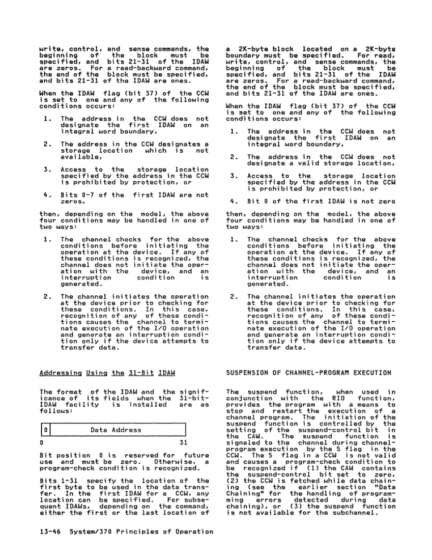
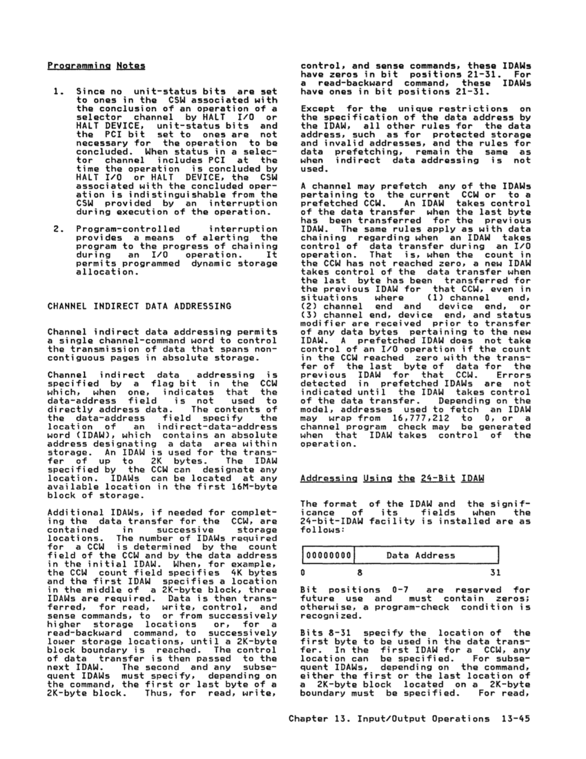
The format of the IDAW and the signif
icance of its fields when the
24-bit-IDAW facility is installed are as
follows:1000000001 Data Address
o 8 31
Bit positions0-7 are reserved for
future use and must contain zeros;
otherwise, a program-check condition is
recognized.
Bits 8-31 specify the location of the
first byte to be used in the data trans
fer. In the first IDAW fora CCW, any
location can be specified. For subse
quent IDAWs, depending on the command,
either the first or the last location ofa 2K-byte block located on a 2K-byte
boundary must be specified. For read,Chapter 13. Input/Output Operations 13-45
1. Since no unit-status bits are set
to ones in the
the conclusion of an operation of a
selector channel by HALT
HALT
the
necessary for the operation to be
concluded. When status in a selec
tor channel includes
time the operation is concluded by
HALT
ation is indistinguishable from the
during execution of the operation.
2. Program-controlled interruption
provides a means of alerting the
program to the progress of chaining
during an
permits programmed dynamic storage
allocation.
a single channel-command word to control
the transmission of data that spans non
contiguous pages in absolute storage.
specified by a flag bit in the
data-address field is not used to
directly address data. The contents of
the data-address field specify the
location of an indirect-data-address
word (IDAW), which contains an absolute
address designating
storage. An IDAW is used for the trans
fer of up to 2K bytes. The IDAW
specified by the
location. IDAWs can be located at any
available location in the first 16M-byte
block of storage.
Additional IDAWs, if needed for complet
ing the data transfer for the
contained in successive storage
locations. The number of IDAWs required
for
field of the
in the initial IDAW. When, for example,
the
and the first IDAW specifies a location
in the middle of a 2K-byte block, three
IDAWs are required. Data is then trans
ferred, for read, write, control, and
sense commands, to or from successively
higher storage locations or, for a
read-backward command, to successively
lower storage locations, until a 2K-byte
block boundary is reached. The control
of data transfer is then passed to the
next IDAW. The second and any subse
quent IDAWs must specify, depending on
the command, the first or last byte of a
2K-byte block. Thus, for read, write,
control, and sense commands, these IDAWs
have zeros in bit positions 21-31. For
a read-backward command, these IDAWs
have ones in bit positions 21-31.
Except for the unique restrictions on
the specification of the data address by
the IDAW, all other rules for the data
address, such as for protected storage
and invalid addresses, and the rules for
data prefetching, remain the same as
when indirect data addressing is not
used.
A channel may prefetch any of the IDAWs
pertaining to the current
of the data transfer when the last byte
has been transferred for the previous
IDAW. The same rules apply as with data
chaining regarding when an IDAW takes
control of data transfer during an
the
takes control of the data transfer when
the last byte has been transferred for
the previous IDAW for that
situations where (1) channel end,
(2) channel end and device end, or
(3) channel end, device end, and status
modifier are received prior to transfer
of any data bytes pertaining to the new
IDAW. A prefetched IDAW does not take
control of an
in the
fer of the last byte of data for the
previous IDAW for that
detected in prefetched IDAWs are not
indicated until the IDAW takes control
of the data transfer. Depending on the
model, addresses used to fetch an IDAW
may wrap from 16,777,212 to
channel program check may be generated
when that IDAW takes control of the
operation.
Addressing Using the 24-Bit IDAW
The format of the IDAW and the signif
icance of its fields when the
24-bit-IDAW facility is installed are as
follows:
o 8 31
Bit positions
future use and must contain zeros;
otherwise, a program-check condition is
recognized.
Bits 8-31 specify the location of the
first byte to be used in the data trans
fer. In the first IDAW for
location can be specified. For subse
quent IDAWs, depending on the command,
either the first or the last location of
boundary must be specified. For read,